Automating a manual antenna tuner

MFJ Versatuner with servo’s, a stepper and a Raspberry Pi

Automatic antenna tuners are expensive, manual antenna tuners are slow. So it has been a long time I dreamed of making my own automatic system.

As this year I was following a raspberry pi class and we needed to make our own project I decided to finally try to make this automatic tuner.

Summary:
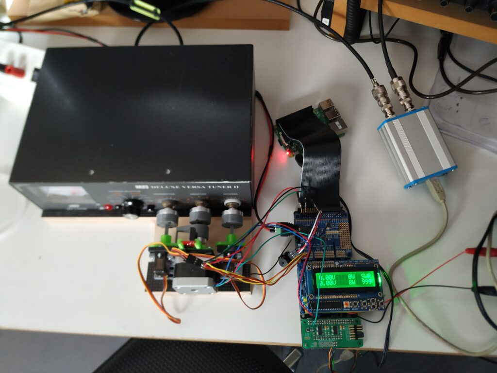
– Forward and reflected power are measured with a Boxa Swr bidirectional coupler combined with an ADC
– SWR is calculated in the raspberry pi and displayed on an LCD
– When SWR is to high an alarm is sounded in CW
– after pushing a button the capacitors and the coil in the tuner are reset to 0. For the capacitors I use 2 servos, for the coil I use a stepper motor. All mechanical connections are made using 3d-printed parts. The reference point for the stepper motor is made using an infrared port.
– next is the tuning operation:
— the ‘transmitter’ capacitor is sweeped over it’s full range and swr is measured every degree. Then this capacitor is returned to it’s best position
— next idem for the ‘antenna’ capacitor
— sweeping operation is repeated for maximum 4 times, if the SWR is below 1,5:1 then tuning is stopped. If SWR is above this limit then the coil is moved to the next setting and the sweeping is repeated
– built in securities:
— all alarms on the LCD and in morse code
— alarm when SWR is to high
— alarm when tx-power is to high for tuning
— coil/stepper can not be switched when there is rf-power

Remarks:
– no tuners have been harmed in any way for this operation!
– Was the raspberry pi the best choice for this? This could probably have been done using some microcontroller instead but the class I followed wat not arduino or esp 32 🙂

A 30w dummy load really can’t handle 100w

Or at least that’s what I found out a few days ago… I was doing some tests on a bidirectional coupler (more about that project in a future post) and I didn’t pay enough attention so I cranked up the power of my transmitter to 100w. And, of course, after a few seconds I got the smell of burned electronics in my shack.
That’s when I decided to go through my junkboxes and find the resistor I once bought to build myself a decent dummyload.
These are the results:

The resistor is an RFP 250-50 TC so this should handle up to about 250w.
SWR between 160m and 6m is max 1.04:1. I have not tested any higher frequencies because my antenna analyser only goes up to 54 MHz.
The heatsink is salvaged from an old telephone switchboard (made by Bell Telephone in 1980).

The AVG Business firewall is stopping my SunSDR2 pro

Today AVG Business (= the paid version of the antivirus software) automagically installed its new version. And, [censored swear word], after restarting my pc, no more connection between my SunSDR and my PC.
Shutting off the firewall solves the problem but is of course not really a long term solution.
I have added the ExpertSDR software and the network address of the SunSDR to the firewall settings but to no avail for now. I guess I’ll have to dig a little deeper to get it running again.

UPDATE: I messed around for a while trying to allow the SunSDR and ExpertSDR to get through the firewall but to no avail. As I use a pretty decent firewall in my router I decided to simply uninstall the AVG firewall component.

Adding the e-coder to the SunSDR

A few weeks ago I decided to add the e-coder to my SunSDR line. The e-coder is an external interface that provides a physical VFO-knob and some buttons and digital encoders to command some (programmable) functions of the SunSDR.

The advantage of the e-coder is that you can switch the programmed functions without having to move the focus from your (contest) logging software.

Apparently the e-coder was not on stock with the supplier even if his website stated otherwise. So the device had to be sent from Russia to the UK and then from the UK to my address. This took about 3 weeks.

Unfortunately the e-coder arrived today and the VFO-knob was pretty loose, it was wiggling about 5mm from one side to the other when I touched it. Whether this was caused by a poor design, by a manufacturing fault or by transport damage, I don’t know yet. I have to say the packaging the supplier sent it in was below (my) standard. A few minutes ago I received an e-mail form the supplier stating ‘Ok, send it back to us we will get it sorted’.

So I guess I’ll have to make a trip to the post office tomorrow. I wonder who’ll pay the shipping costs…

SSB with the SunSDR2 pro

For those knowing me, I haven’t done a lot of SSB in the last few years. I mostly do digital with a large preference for RTTY contests.

During the month of may the UBA (Belgian Amateur Radio society) celebrated its 70th birthday and we could activate the special event callsign OT70TRA (there were about 50 OT70 stations active).

For this activation I wanted to do some SSB also and the pileups where very nice. But of course with a handmike it’s not that comfortable to rapidly enter QSOs in the log.

That’s when I decided to find my good old Heil headset with a HC4 element and connect it to the Mic1 connector. I guess I was lucky as this worked from the first try. Audio reports were very good, even without changing anything in the equalizer settings of the Pro2.

ON5MF is still fond of SDR (of course)

It’s a long time I haven’t written anything about the SunSDR but apparently some people even read what I write here 🙂

So what did I do in the last 15 months?

First of all I got frustrated with the limited power (15W) so I added a HLA305v PA to my system. The HLA305v is a fairly low-cost solid state amplifier rated at approximately 300W. According to the tests of the ARRL it should be reasonably clean when using it in low power mode (+/- 200W out on the low bands, +/-100W out on 10m).

But when installing the HLA305v I had a problem, all wiring was correct and the amp went into transmit when pressing the PTT on the SunSDR but 90% of the time the automatic bandfilter switching in the amp did not work. After some research I tested with a small relay between the transceiver and the amp and this solved the problem.

When this worked as a prototype I made a little breakout box for all ports of the SunSDR:

The relay for the ptt is inside the 3-d printed box, and I have all output pins easily available now.

DX spot analysis

I am sorry to say but I had to (temporarily?) stop the analysis of dx-spots because it was getting to expensive. Every few weeks the Raspberry Pi seemed to completely corrupt its SD-Card or the thumb drive with the software. I have been trying very hard but I can’t seem to find any reason why it’s doing this.

For now I am thinking about running the same software on a pc. But of course like all HAMs I have a lot of projects…

If you miss it please let me know, maybe it will increase my motivation to get it back on the net.

I learned a lot and I had a lot of fun with this experiment.

ON5MF goes SDR (8)

In the last few weeks I have not done too much with the SunSDR except make a few hundred QSOs. This is fun!

The only real thing I changed was to print 2 brackets on the 3d printer to mount an 8 cm fan above the transceiver. For now I have this 12v fan running from the same 15v supply as the transceiver but I put 8 diodes in series to get the voltage for the fan down to about 6v. The fan runs very quiet and the max temp I have seen in ExpertSDR since I use the fan is 30°C while making QSOs in JT65.

If you want to print your own brackets, please let me know, I’ll send you the STL-file. Or for those living nearby I can print them for you.

ON5MF goes SDR (7)

  •  Day 9
    • after testing a few freeware or donationware VACs (Virtual Audio Cables) I finally decided to purchase Virtual Audio Cable from Fox magic software. VB-Cable worked but I couldn’t use the windows controls to set the audio levels. And we all know if you don’t watch your audio level on tx that your signal is almost certain to be overdriven.
      Installation of VAC was pretty easy, I just followed the instructions from VAC itself and it worked like a charm first try.
    • In the meantime I also installed an old computer ventilator over the heatsink of the SunSDR. With a potentiometer in the 12v line I get no noise at all but it keeps the trx a few degrees cooler. In the future I’ll probably use the thermostat feature in the trx but for now I have other things to do.
    • Even with the new version of the software I still intermittently have the tx-problem mentioned previously but this morning I got an email from Vasily that he found and corrected the bug and that he will publish a new version of the software in the next few days.
    • After setting the offset for PSK the same in ExpertSDR as in Winwarbler I was able to make my first few PSK31, PSK63 and PSK125 QSOs.
    • Setting up Commander to switch DXlab to the same mode as ExpertSDR took some experimentation but these are the settings that seem to work for me now, at least for PSK. I’ll test RTTY in the next few days.

      general-tab     psk-tab

  • Todo:
    • connect transceiver CAT to N1MM+
    • find suitable parameters for RTTY and for JT-modes
    • connect ventilator to SunSDR thermostat
    • connect Heil Pro-Set 4
    • find a suitable PA to get at least 100W
    • is it possible to make my own E-coder using an Arduino or Teensy?

ON5MF goes SDR (6)

  • Day 8
    • the TX problem is back… Sometimes after starting the software the TRX does not want to TX. But if it has been into TX once it keeps working as long as the software is running. A hardware or a software problem???? I have sent a mail to the SunSDR customer support.
    • Now that the CAT is working I tried to get a virtual audio cable running so that I can make some QSO in digital modes. I installed VB-cable and I can RX and TX in DXlabs Winwarbler.
      But for now I couldn’t figure out how to lower the tx audio volume as not to overdrive the afsk-signal. The VB-cable VAC does not seem to respond to the normal Windows7 audio controls.
      This will need some further experimentation.