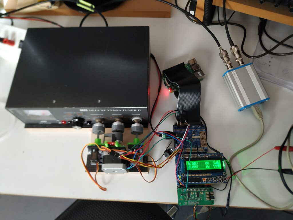
Automatic antenna tuners are expensive, manual antenna tuners are slow. So it has been a long time I dreamed of making my own automatic system.
As this year I was following a raspberry pi class and we needed to make our own project I decided to finally try to make this automatic tuner.
Summary:
– Forward and reflected power are measured with a Boxa Swr bidirectional coupler combined with an ADC
– SWR is calculated in the raspberry pi and displayed on an LCD
– When SWR is to high an alarm is sounded in CW
– after pushing a button the capacitors and the coil in the tuner are reset to 0. For the capacitors I use 2 servos, for the coil I use a stepper motor. All mechanical connections are made using 3d-printed parts. The reference point for the stepper motor is made using an infrared port.
– next is the tuning operation:
— the ‘transmitter’ capacitor is sweeped over it’s full range and swr is measured every degree. Then this capacitor is returned to it’s best position
— next idem for the ‘antenna’ capacitor
— sweeping operation is repeated for maximum 4 times, if the SWR is below 1,5:1 then tuning is stopped. If SWR is above this limit then the coil is moved to the next setting and the sweeping is repeated
– built in securities:
— all alarms on the LCD and in morse code
— alarm when SWR is to high
— alarm when tx-power is to high for tuning
— coil/stepper can not be switched when there is rf-power
Remarks:
– no tuners have been harmed in any way for this operation!
– Was the raspberry pi the best choice for this? This could probably have been done using some microcontroller instead but the class I followed wat not arduino or esp 32 🙂

