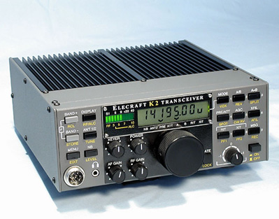
Yes, this is the new toy I built! As of the beginning of december 2006, the standard version is completely assembled and aligned.
Why did I choose to build a kit you’ll ask? Well, there are a few reasons:
- Since a long time I have the feeling that to be a “true” radioamateur you also have to be able to build some gear yourself. In the past I have built some small kits but nothing really as challenging as a real transceiver. Or, more simply stated, I wanted to get rid of the label PLUG-AND-PLAY-AMATEUR
- New commercial transceivers are great, they have lots of bells and whistles but, have you ever tried to get a rig serviced that is 3 or more years old? If I’m not able to do it myself I think I have a better chance to find someone who can fix my K2.
- see also the FAQ on this site…
The choice for the K2 instead of any other kit was pretty easy:
- There are very little transceivers getting a score of 4.9 out of 5 on EHAM
- This rig has all (well most) of the features you need in a HF transceiver
- If only we could get as much -FREE- support for any gear in our house as you get on the Elecraft mailing list, life would be a lot easier
- As written by Jeff Davis, KE9V in his blog:Think about it, when fully filtered to ‘better’ the K2 performance a user would have to spend $4400 for an Orion. That is SEVEN times the cost of a K2. The new Icom is a mere EIGHTEEN times more costly. The new Yaesu will no doubt have a similar price tag.
But even then I had some doubts when I had ordered my toy…: Would I ever be able to get this rig up and running or would it end with the other junk in some dark dusty corner of my attick?
Preparations
- First of all I needed a dedicated space so I put an extra table in the shack (it was easier to put an extra table than to clean up the mess on the other ones…)
- I invested in a good temperature-controlled soldering station and a magnifier lamp. All other (small) tools were already somewhere in my shack, so I only had to gather them and put them in a few drawers so I could find them easily when needed.
- Finding solder within Elecraft specs was not very easy either (Radio-Shack has stopped its activities in Belgium ages ago…) but thanks to a hint from Peter from QRPProject I could find something suitable.
- I also read a lot of info on different websites about constructing kits and constructing the K2 in particular. Apart from the site of Elecraft itself these were also pretty helpful:
- www.n0ss.net (general info about kit building and some pages about the K2) especially the pdf-file SOLDERING TIPS, Useful Soldering Hints was very helpful
- De-soldering Primer (using your chin, etc.) if you stay up late to build your kit, you’ll certainly need this once in a while!
- Elecraft list archive I downloaded all the files and imported them in Thunderbird so it was far easier for me to search in these archives than through the web interface.
Construction of the basic kit
- First impressions
When opening the package I was pretty overwhelmed, wow, this is a BIG project for me (yes the doubts began to rise again..). But, I also noticed the professional way everything was packaged in a few dozen different bags according to the use and type of components.
As you certainly noticed on the website here, English is not my mother tongue but the manual seems clear enough for me to be able to finish this project. But it’s time you guys over the pond start to use metrics instead of the imperial system, those inches are pretty confusing to us (hihi).
As in all user manuals there are some mistakes/updates but the K2-manual comes with a list titled ‘K2 KIT CHANGES AND MANUAL ERRATA’ so the first thing I did was go through the manual and made the necessary changes.- Inventory
The complete inventory took me a little less than 4 hours, but being a not so experienced builder, it helped me to get familiar with the different parts.
This is also where I made my first mistake… I should have sorted all parts during the inventory instead of putting them back in the small bags they came in. This would have spared me a lot of time later on during the construction.
If I counted correctly there are 867 parts in the basic K2 kit! And, not one part was missing!- Control Board assembly
After sorting the components (yes I should have done that during the inventory…) I got started.
These are also my first solderings with my new Weller station. I SHOULD HAVE REPLACED MY OLD SOLDERING IRON AGES AGO!!!!
The construction starts pretty easily, with a few resistors and the difficulty rises slowly.
Pretty considerate of the guys as Elecraft to put the resistors in a tape in the correct order you need them! It helps avoiding lots of mistakes!
Except for a transistor I had to unsolder and put back in because it was too high above the board, no real difficulties here.
The visual inspection and resistance checks show no problems.- Front Panel Board assembly
After sorting the components (yes again), I tried to figure out how the ‘pushbutton switch spacing tool’ worked. Great trick to get all those buttons aligned correctly!
It’s clear the difficulty is increasing gradually. But, except for a litle fight with the double-backed tape for the green plastic bargraph filter, again no problems here.
At least now it starts to look like a transceiver!
Visual inspection and resistance checks OK.- RF Board assembly and test, part I (control circuits)
Not too many components to mount in this part.
Visual inspection and resistance checks OK.
This is the first time the Control Board, Front Panel Board and RF Board have to be assembled, and power has to be applied… Cross your fingers, say a little prayer, push the Power switch Mmm, no smoke?, wow! And the display says ‘INFO 201’ as it should. Switch it off, switch it on again and it says ‘Elecraft’. IT’S ALIVE!!!!! Time for a litle party!
No problems encountered in the further tests and first alignments.- RF Board assembly and test, part II (receiver and synthesizer)
Time to disassemble the different printed circuit boards and go on with the construction.
This is the part where I made my second mistake… placed a capacitor in the wrong spot and had to unsolder it. Here most tricks of the De-soldering Primer mentioned above had to be applied. Of course the capacitor was destroyed in the operation and the local shop didn’t have any to replace it. Luckily there were some more of the same value in the kit and by the time I needed those the replacement had arrived from a mail-order company.
During construction I had some doubts about how to install some of the crystals but the question I asked over the Elecraft reflector was answered in about 10 minutes…
The most dreaded part in the construction of the K2 must no doubt be the winding and installing of the toroids. I know, you can order them ready made from ‘The toroid guy’ but I wanted to have the full experience so I decided to wind them myself. I had to start over several times because I seemed to repeatedly tend to wind the wire in the wrong direction, but after a few tries all went well. I prepared the leads using the “solder blob”-method (look halfway down the page). After all, there is no reason to worry about those toroids, when you follow the given descriptions, everything goes pretty smoothly.
All tests and alignments went according to specs, except for some doubts about the I.F. Amplifier Alignment for which I couldn’t really find the best position. A quick question through the reflector solved this.- RF Board assembly and test, part III (transmitter)
No problems encountered during this part of the construction. Upon visual inspection I noticed one forgotten soldering and I reheated a few solderings who looked suspicious to me.
Finally the different small boxes of parts seem to get empty (hi)
All alignments seem to go pretty well, using the limited tools at hand (Digital multimeter / RF Power meter / 50 Ohm dummy load / Fequency counter / PC with spectrumanalyser software).- Final assembly
Nothing really difficult here, just a few connectors to mount, and before you know it you are at page 80 of the manual: “This completes assembly of your K2”. Hey, it’s finished already? I had so much fun building it that I almost regret it being finished.
First results
The transceiver seems to work according to specs, power output is OK on all bands, RX-sensitivity is OK as far as I can measure using the Elecraft XG2
(Semi-)professional measurements
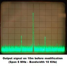
Together with ON7KZ (Tnx Luc!) we did some measurements using his spectrum analyser and as you can see on the picture (taken on 10m, spurious down about -38 dB) the output signal on some bands (10, 12, 15 and 80m) wasn’t very clean…
But, with some hints from Don W3FPR (Tnx!) we could trace back and found out the problem started in the buffer. When we decreased the gain of the buffer by adding a resistor of 1.5 kOhm parallel to R93 (820 Ohm), the spurious decreased with about 10 dB!
Moreover, when only using about 90% of maximum output power the spurious disappeared completely! And on QRP, if you can’t work’em with 9 watts, you won’t work’em with 10 watts either…
After some more feedback from Don W3FPR and Gary AB7MY it seems this problem needs more investigation.
So K2 sn 5549 is not ready to get on the air yet…
Construction of the options
No options ordered yet, but that’ll happen VERY soon, maybe, and who knows, Santa?
Conclusion
I didn’t really encounter big difficulties while constructing this rig. The few questions and issues I had were VERY rapidly solved through the Elecraft forum (TNX guys, you’re great!). The doubts I had before starting have completely disappeared and I’m already looking forward to construct another (Elecraft?)-kit.
K2 Bookmarks

