Am I the only one finding it difficult to find the ctrl-alt-down key combination to tune to the next mult in N1MM+ logger when I am 30hrs into a contest?
This is the solution I made for it: an extra keypad that emulates these key combinations (or whatever key combination you want to program):
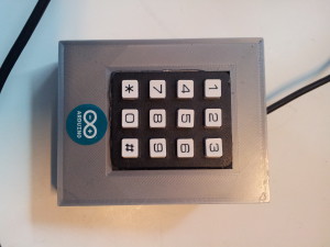
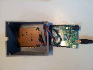
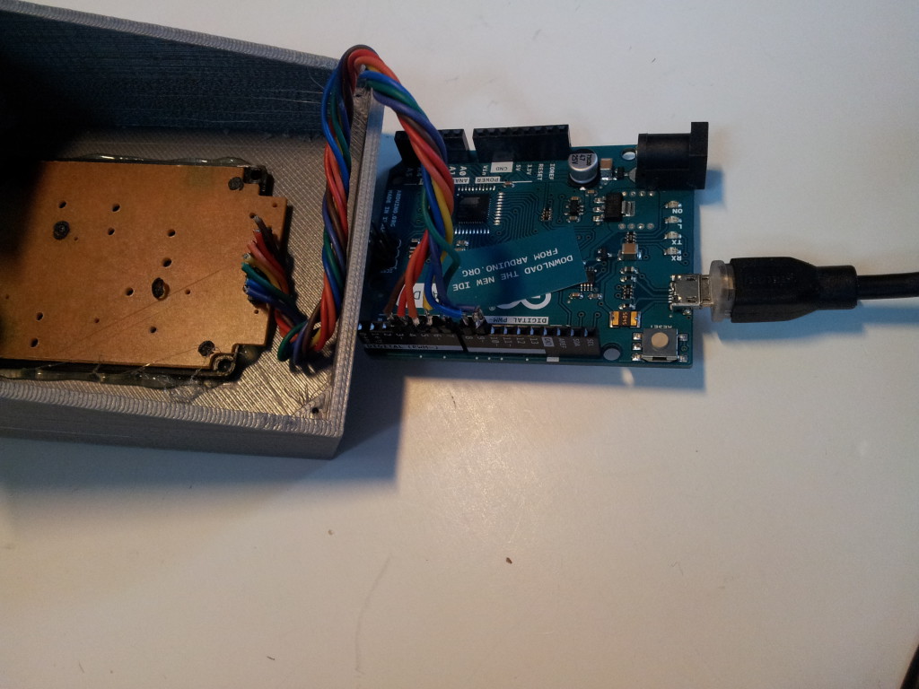
The core is an Arduino Leonardo with a 12 key keypad. These keypads can be salvaged out of an old phone or purchased online. Of course if you need less keys you can use pushbuttons also.
I printed the case with my Delta Rocket 3d-printer.
For the complete beginners with Arduino there is a lot to be found on the net. I found this Instructable very helpful.
This is a pretty easy project, the 2 hardest things are to figure out how the matrix of the keypad is to be wired and what keycodes you need to send to the computer.
In most helpfiles for the Arduino they say that the Leonardo sends ASCII to the computer but this is not true. In fact the Leonardo sends keycodes and they are based on the configuration of the ‘real’ keyboard that is connected and configured in Windows (or any other operating system I guess). As far as I could test the Leonardo uses the same keyboard ‘layout’ as the standard US QWERTY keyboard. So for us Belgians with our AZERTY keyboards it’s not as simple. I had to try out dozens of combinations before finding the correct ones.
For now this is the code I use (not all keys are implemented as of now):
/*
ON5MF/OQ6A Arduino Leonardo Keypad

I did not really 'invent' this myself, I only implemented stuff found on the net. Please feel free to use,
copy, enhance this code at your own will.

If you use it for commercial purposes I'd like to receive at least 50% of the gains ;-)

If you like the code or if you find some enhancements or improvements please let me know.

73 es have fun with it.

Jurgen ON5MF
www.on5mf.be
*/

/*
v001 = testing if keypad works
v002 = added ctrl-left and ctrl-right
v003 = next spot up and down
*/

/* keys and functions
 1  next spot up left radio   ! ctrl-left ctrl-up
 2  Escape                    ! esc
 3  next spot up right radio  ! ctrl-right ctrl-up
 4  next spot dwn left radio  ! ctrl-left ctrl-dwn
 5  back to CQ frequency      ! alt-Q
 6  next spot dwn right radio ! ctrl-right ctrl-dwn
 7  next mult up left radio   ! ctrl-left ctrl-alt-up
 8  turn rotator              ! alt-j
 9  next mult up right radio  ! ctrl-right ctrl-alt-up
 0  swap radios               ! alt-F5
 *  next mult dwn left radio  ! ctrl-left ctrl-alt-dwn
 #  next mult dwn right radio ! ctrl-right ctrl-alt-dwn
 */

//Libraries
#include <Keypad.h>
//----- end of libraries

//Constants
const byte ROWS = 4; //four rows
const byte COLS = 3; //three columns
//----- end of constants

//Variables
//define the symbols on the buttons of the keypads
char hexaKeys[ROWS][COLS] = {
  {'1', '2', '3'},
  {'4', '5', '6'},
  {'7', '8', '9'},
  {'*', '0', '#'}     //ok
};
byte rowPins[ROWS] = {4, 9, 8, 6}; //connect to the row pinouts of the keypad
byte colPins[COLS] = {5, 3, 7}; //connect to the column pinouts of the keypad
char ctrlKey = KEY_LEFT_CTRL;
char leftKey = KEY_LEFT_ARROW;
char rightKey = KEY_RIGHT_ARROW;
char upKey = KEY_UP_ARROW;
char downKey = KEY_DOWN_ARROW;
//----- end of variables

//initialise Keypad
Keypad customKeypad = Keypad( makeKeymap(hexaKeys), rowPins, colPins, ROWS, COLS);
//----- end o initialise Keypad

void setup() {
  Serial.begin(9600);
  Keyboard.begin();
}

void loop() {
  char customKey = customKeypad.getKey();
  if (customKey == '1') {
    Keyboard.press(ctrlKey);
    Keyboard.press(leftKey);
    delay(100);
    Keyboard.releaseAll();
    delay(100);
    Keyboard.press(ctrlKey);
    Keyboard.press(upKey);
    delay(100);
    Keyboard.releaseAll();
  }
  if (customKey == '4') {
    Keyboard.press(ctrlKey);
    Keyboard.press(leftKey);
    delay(100);
    Keyboard.releaseAll();
    delay(100);
    Keyboard.press(ctrlKey);
    Keyboard.press(downKey);
    delay(100);
    Keyboard.releaseAll();
  }
  if (customKey == '7') {
    Keyboard.press(ctrlKey);
    Keyboard.press(leftKey);
    delay(100);
    Keyboard.releaseAll();
  }
  if (customKey == '*') {
    Keyboard.press(ctrlKey);
    Keyboard.press(leftKey);
    delay(100);
    Keyboard.releaseAll();
  }
  if (customKey == '3') {
    Keyboard.press(ctrlKey);
    Keyboard.press(rightKey);
    delay(100);
    Keyboard.releaseAll();
    delay(100);
    Keyboard.press(ctrlKey);
    Keyboard.press(upKey);
    delay(100);
    Keyboard.releaseAll();
  }
  if (customKey == '6') {
    Keyboard.press(ctrlKey);
    Keyboard.press(rightKey);
    delay(100);
    Keyboard.releaseAll();
    delay(100);
    Keyboard.press(ctrlKey);
    Keyboard.press(downKey);
    delay(100);
    Keyboard.releaseAll();
  }
  if (customKey == '9') {
    Keyboard.press(ctrlKey);
    Keyboard.press(rightKey);
    delay(100);
    Keyboard.releaseAll();
  }
  if (customKey == '#') {
    Keyboard.press(ctrlKey);
    Keyboard.press(rightKey);
    delay(100);
    Keyboard.releaseAll();
  }
}
